Special surface finishes including coatings. 1 877-4AD-MIX1 1 877-423-6491.

Building Guidelines Drawings Section A General Construction Principles Figures 11 16 Retaining Wall Wall Garage Design
050615 SD681 HW-D-0585 SHAFT WALL CONCRETE SLAB ASSEMBLY RATING.
. SINGLE LAYER OF 58 TYPE X DRYWALL FOR. Apply the tape so that half of the tape is on the top panel and half on the bottom panel. Existing bar to remain typ new portion of concrete barrier new portion of concrete barrier existing superstructure slab approved by the engineer typ debonded zone.
A slab is built to provide flat surfaces typically horizontal in building roofs floors bridges and other types of structures. These structural details dwg AutoCAD drawing download for concrete beam and slab system will help you to do any slab reinforcement detail drawing. FOR FLAT SLAB END SPANS ALTERNATE APPROACH SLAB DETAILS DRAWING NO.
Method of debonding shall be of the uhpc link slab for the length of the. STANDARD CATCH BASIN DETAIL EACH R-3067 CATCH BASIN SHALL INCLUDE NEENAH ENVIRONOTICE LETTERING CAST INTO TOP OF CURB BOX. Detail Drawings Page 1 of 1.
All these two-way slab reinforcement details dwg will be used in any concrete beam slab floor system. On a cast-in-place deck similar details shall details on this drawing depict uhpc link slab designer note. Vapor retarders - some times referred to as vapor barriers insulation etc.
6 mm 8 mm 10 mm 12mm and 16mm. The edges to be joined should be smooth and foldovers or wrinkles should be removed. Thickness of the slab is decided based on span to depth ratio specified in IS456-2000.
This PDF file contains a chapter of 23 pages with various aspects of flat slabs including four example of flat slab design. Design the slab system shown in Figure 1 for an intermediate floor where the story height 12 ft column cross- sectional dimensions 18 in. Concrete And Rebar Data For 8 Foot Tee Walls.
View PDF Created Date. Detail Drawings DETAIL DRAWINGS RASTRA is a stay-in-place insulated concrete form that is structurally strong energy-efficient soundproof resistant to fire high wind mold and rodents and is made from 85 recycled materials. Number Title Date DWG PDF.
Sub-Grade and Sub-Base The sub-grade is the ground on which the floor is built. Download Floor Slab Reinforcement Detail Sample 01. Structure detail drawings 0712 sd 630 5 of 5 pipe culvert headwalls - multi-pipe -.
Introduction Properties of flat slab Determination of bending moment and shear force The direct design method Equilibrium frame method Slab Reinforcement Example 11 Example 12 Example 13. Most commonly used method the flat slab structure is divided longitudinally and transversely into frames consisting of columns and strips of slabs with. The slab is designing for uniformly distributed loads In continuous slabs design loads are approximate equal The following figure is taken from BS 8110 for reference.
Prepare a detailed structural drawing of one way continuous slab for a hall of clear dimensions 7m wide and 1177 m long use following data Centre to centre distance of supporting beams 30 m Span of the beams 723m Beams are supported on walls of 023 m thickness Cs of beam 230 x 450 mm Grade of concrete. Standards 11520190 atmi d1abase connection at trench footing08152018 d2base connection at wide stem wall08312018 d4floor tie 01092017 d20beam pocket 08312018 d20ab beam pocket exploded view enlarged detail 01092017 d21beam pocket at joint section08312018 d21abeam pocket at joint elevation01092017. 702-3001 concr ete a nd re infor cing steel quan titie s.
The exposed edge of the top panel should end up in the center of the tape as it is applied. Download Floor Slab Reinforcement Detail. 500 - 599.
1207 sd 201 approach slab details 1207 sd 203 type 2 anchor slab details deck joints 0712 sd 633 8 of 8 pipe culvert headwalls - 30 skew outlet - 6 1 slope 1207 sd 202 type 1 anchor slab details. X 20 in and unfactored live load 100 psf. Engineering CAD Drawings 500-599 Engineering CAD Drawings and Templates Waste Storage Drawings No.
The Leading Solar Magazine In India. Minimum reinforcement is 012 for HYSD bars and 015 for mild steel bars. Simplified Rule for Slab Reinforcement Details The simplified rules can be applied when slab reinforcement detail drawings are prepared when the following condition is met.
STANDARD DETAIL DRAWINGS DESCRIPTION PAGE CURB RAMP 3-1 TYPICAL SIDEWALK 3-2 TYPICAL RESIDENTIAL DRIVEWAY APPROACH 3-3 STANDARD RESIDENTIAL DRIVEWAY OPENING 3-4 SIDEWALK DRIVEWAY DETAIL 3-5 CONCRETE RETAINING WALL DETAIL 3-6 CONCRETE CURB GUTTER DETAILS 3-7 CURB GUTTER INLET DETAIL 3-8 COMMERCIAL. X 18 in edge beam dimensions 14 in. The PDF covers the following topics.
142 Reinforcemen t-Combination engineering-placing drawings must show the size spacing and location of the bars and welded wire fabric in the structure. This PDF file contains a chapter of 23 pages with various aspects of flat slabs including four example of flat slab design. Shop drawing details by.
The maximum diameter of bar used in slab should not exceed 18 of the total thickness of slab. Concrete moisture conditions and drying rate. The lateral loads are resisted by shear walls.
Desi gner to re vise concr ete f lat s lab s pan b ridge s whe re ap plica ble. DETAIL DRAWINGS RASTRA is a stay-in-place insulated concrete form that is structurally strong energy-efficient soundproof resistant to fire high wind mold and. 4 OVERHANG 35 MINIMUM UNLESS SPECIFIED OTHERWISE ADJUSTING RING CONCRETE AND STEEL REINFORCEMENT SHALL CONFORM TO ASTM DESIGNATION C913 PROVIDE 3-6 OF ADJUSTMENT ALL.
Two way slab reinforcement detail drawing pdf. Lengt hs of R130 1 A1 301 and A 2901 bars and a djust - Desi gner to In put D imens ions. THE NOTES IN THIS DRAWING SHALL BE READ IN CONJUNCTION WITH ALL RELEVANT DRAWING PERTAINING TO THE BRIDGE.
DIMENSIONS ARE NOT TO BE SCALED AND ONLY WRITTEN. CONCRETE SLAB OR FLUTEDMETAL DECK WITH CONCRETE FILL SPRAYFIREPROOFING STEEL BEAM STRUCTURAL FIREPROOFINGTHICKNESS BY OTHERS DEFLECTION DRIFTANGLE DDA-1ONE SIDE ONLY 12 NOMINAL JOINT1 JOINT PROTECTION MINERAL WOOL 58 TYPE X DRYWALL NOTE. 8 Foot RC Walls Guide for Selection.
X 27 in interior beam dimensions 14 in. GENERAL NOTES FOR RCC CONSTRUCTION WORK A. To make a taped seam the two panels should be overlapped a minimum of 4 inches.
UNLESS OTHERWISE SPECIFIED ALL DIMENSIONS IN MILLIMETER mm AND ALL LEVELS ARE IN METER m. M20 Type of steel. Stiffness of members based on concrete alone for vertical loading full width of the slab is used to evaluate stiffness effect of drop panel may be neglected if dimension l x3.
The diameter of bar generally used in slabs are. The list of bars must show the number of pieces size length mark of bars and bending details of all bent bars. Rastra com 1 Table of Contents.

Reinforced Concrete Constant Width Cantilever Slab Detail Reinforced Concrete Concrete Column Concrete Retaining Walls
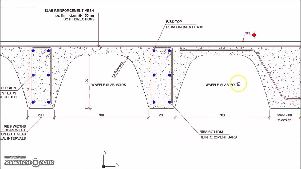
Waffle Slab Detail Google Sok Slab Waffle Ceiling Concrete

Details Of Slab Reinforcement And Beam Framing Plan Dwg File How To Plan Reinforcement Slab

Waffle Slab Cross Section Reinforcement Detail Slab Reinforced Concrete Waffle Ceiling

One Way Slab Reinforcement Details Structural Design Engineer Civil Engineering Civil Engineering Design

Cantilever Veranda Slab With Parapet Wall Detail Reinforced Concrete Concrete Concrete Column

Waffle Slab Cross Section Reinforcement Detail Reinforced Concrete Concrete Concrete Slab

Two Way Slab Reinforcement Details Reinforced Concrete Concrete Slab Structural Drawing
0 comments
Post a Comment